Scope of Application:
If you’re looking for reliable and mature sandblasting equipment for the inner wall of enamel inner tanks, you’ve come to the right place. Our state-of-the-art sandblasting equipment is designed to treat inner tanks with a diameter range of φ240 to φ500 and a length of up to 1500mm. The equipment fully complies with national standards and general technical specifications related to sandblasting operations. We’ve selected the most reliable technologies that have been successfully applied without experimental factors. Our equipment design and layout prioritize ease of use and maintenance, ensuring efficient and hassle-free operation. Trust us for all your sandblasting equipment needs.
Process Plan
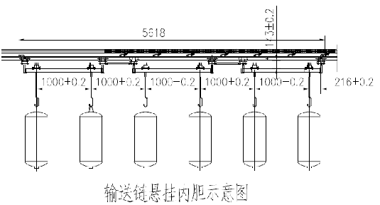
This process involves treating four inner tanks simultaneously using a continuous hanging conveyor chain inside a sandblasting box. The inner tank is hung vertically with a special hoisting device, and it automatically enters the sandblasting station from one end of the sandblasting box based on the program for sandblasting treatment. Once the sandblasting treatment is completed, it is sent out from the other end of the sandblasting box using a fully automatic operation method.
The sandblasting treatment is carried out by rotating the inner tank and lifting the spray gun. Our equipment is equipped with an internal tank detection function, meaning sandblasting is carried out if there is an inner tank on the hook. No sandblasting is carried out if there is no inner tank. However, it is important to note that the model of the inner tank hung each time must be consistent.
Our sandblasting treatment offers an efficient and reliable method for cleaning electric water heaters’ inner walls. With our state-of-the-art equipment, you can rest assured that your inner tanks will receive a thorough and high-quality sandblasting treatment. Contact us today to learn more about our services.
The processing method operates fully in automatic mode
Sandblasting Nozzle: A dedicated porous composite nozzle is used for efficient sandblasting treatment of all surfaces inside the inner wall of tanks. This process helps to thoroughly clean steel sand and dust particles inside the inner tank. Additionally, an air gun is installed at the discharge port of the inner tank outside the sandblasting box. This allows workers to manually clean and sandblast the inner tank, ensuring a complete and thorough cleaning process in one go
The equipment set comprises various components including a suspension chain conveyor, a sandblasting box, a filter cartridge dust collector, a fan, two separators, two sandblasting machines, two sets of (4-gun) gun movement mechanisms, four sets of inner tank rotation mechanisms, four sets of inner tank positioning and clamping mechanisms, two sets of diameter conversion mechanisms, and a control system.
Working mode
The sandblasting plan is fully automatic, with manual loading and unloading of the inner tank performed by workers. The sandblasting operation in the sandblasting box is automatic, and after sandblasting is completed, automatic air blowing and sand cleaning can be carried out. A thorough cleaning may require manual cleaning by workers at the unloading station.
Characteristics of the sandblasting line:
-
- 3.1 Automatic conveying and processing of workpieces using advanced and highly automated enclosed track suspension chain to transport workpieces and perform automatic sandblasting in the sandblasting box.
-
- 3.2 One-time treatment for thorough cleaning of the inner wall of the tank. A three-hole composite nozzle is used to perform sandblasting on the inner wall of the steel tank, achieving full cleaning of the inner tank.
-
- 3.3 Automatic addition of abrasive during sandblasting, with automatic stopping when it’s full.
Environmental protection: The environmental issues involved are industrial dust, vibration, and noise.
-
Industrial dust emissions: During sandblasting, industrial dust will be generated. The countermeasures are to set up a ventilation and dust removal system, the emission concentration after purification is less than 100mg/m3, and the emission efficiency is less than 3.5kg/h, which is lower than the national standard.
-
Vibration: The main equipment that generates vibration in the entire system is the fan. The countermeasures are to equip the fan with a vibration reduction device and a vibration reduction connector (soft connector).
-
Noise: There are two types of noise generated: The first type is the noise from the fan. The countermeasures for fan noise are: selecting low-noise fans and installing silencers at the air outlet. The second type of noise is the aerodynamic noise at the nozzle outlet during sandblasting and the collision noise when the steel sand hits the steel plate. The countermeasure is to carry out sandblasting in the enclosed sandblasting box and steel tank during nozzle operation.
Overall, the sandblasting equipment for the inner walls of hot water heaters has environmental benefits when proper countermeasures are taken against industrial dust, vibration, and noise. These measures ensure that the emission concentrations and efficiency are lower than national standards and that the fan is equipped with a vibration-reduction device and soft connector. By selecting low-noise fans and installing silencers at the air outlet, the noise generated by the fan can also be reduced. To minimize the second type of noise, sandblasting should be carried out in an enclosed sandblasting box and steel tank during nozzle operation.
Main Technical Parameters and Technical Requirements
- Applicable bottle size and type: This sandblasting equipment is designed for sandblasting the single inner tank of a water heater with a diameter of φ240-φ500 and a length of ≤1500mm. The inner tank material is SPCC or SPHC low carbon steel plate, and the workpiece thickness is cylinder body 1.5-2.5mm and the end cap 2-3mm.
- Bottle mouth diameter: The bottle mouth diameter must be ≥φ50mm to ensure that it can fit into the sandblasting equipment.
- Nozzle: The sandblasting equipment is equipped with a small three-hole nozzle for blasting.
- The maximum load-bearing capacity of a single hook for hanging lifting equipment: The sandblasting equipment can handle a maximum load of 100kg with a single hook for lifting.
- Maximum line speed of conveyor chain: The maximum line speed of the conveyor chain is 12m/min, which can be adjusted with frequency conversion speed regulation.
- Power supply: The power supply required for the sandblasting equipment is 380V/50Hz±10%.
- Power: The total power consumption of the sandblasting equipment is ≤18Kw (excluding the power of the air compressor unit).
- Gas source conditions: The sandblasting equipment requires clean air with an oil content of ≤0.1 PPm, water content of ≤1.3 g/m3, pressure of 0.7-0.8 Mpa, flow rate of ≥40m3/min, and air storage tank of 0.8 Mpa and ≥5 m3.
- Surface preparation grade: The surface preparation grade of the workpiece after sandblasting treatment should be Sa2-Sa2.5 (GB8923-88).
- Production capacity: The sandblasting equipment has a production capacity of 80 units/hour (60L as an example).
- Environmental standards: The dust emission from the sandblasting equipment meets national environmental protection standards (≤120mg/m3).
- Visual inspection: The surface preparation grade of the workpiece after sandblasting treatment should be determined by visual inspection.
- Automatic recording: The sandblasting equipment automatically records the number of inner tanks sandblasted.
- Abrasive type: The sandblasting equipment uses steel shot or steel sand with a diameter of φ0.5-1.2mm (G25:G40=2:1), manufactured by Qingdao Bailida or Shanghai Morgan.
- Automatic recovery and separation: The abrasive used in the sandblasting equipment is automatically recovered and separated.
- Distance between the centers of the two inner tanks during sandblasting treatment: The distance between the centers of the two inner tanks should be 1000mm.
- Operator requirements: At least 3 operators are required to operate the equipment (1 person for installing the inner tank, 1 person for unloading the inner tank, and 1 person for inspection, observation, and inner tank transfer).
- Maximum equipment elevation: The maximum equipment elevation is ≤+5.6m. The equipment requires a pit, and the pit depth should be ≤5.4 meters (subject to the final design).
- Equipment layout: The total area occupied by the sandblasting equipment should be in accordance with the “4 Inner Tank Sandblasting Equipment Layout”.
Working Principle
After the inner container is transported to the sandblasting station, it automatically stops. The sandblasting box door closes automatically, and the positioning clamping mechanism automatically positions and clamps the inner container. The rotating motor drives the inner container to rotate, while the spray gun lifting motor moves the spray gun up and down to extend into the inner container for sandblasting. Upon completion, the conveying chain transports the inner container to the next station for manual sand cleaning before transferring to the next process. The abrasive and dust are collected in the sand collecting hopper for backup.
When the sandblasting machine requires additional abrasive, the material feeding valve beneath the sand-collecting hopper opens. The abrasive is then delivered to the sandblasting tank through the shot pipe or BE separator. The dust undergoes dedusting through the dedusting air duct and filter cartridge deduster before being discharged into the atmosphere from the fan’s exhaust port. The exhaust pipe is connected outside the workshop.
The automatic process of the sandblasting production line can be summarized as follows:
- After the inner container arrives at the sandblasting workstation, the box door closes, and the positioning clamping mechanism positions and clamps the workpiece.
- The rotating motor rotates the inner container.
- The spray gun lifting motor extends the spray gun into the inner container, performing segmented sandblasting based on the inner container’s shape.
- The spray gun continues to rise until it reaches the top of the inner container before descending.
- Sandblasting stops once the spray gun reaches the stopping position.
- The spray gun rises again, blowing compressed air to clean the sand inside the container.
- After the air blowing and dust cleaning, the spray gun descends.
- When the spray gun reaches the stopping position, its rotation and movement stop, and the positioning clamping is released simultaneously.
- The box door opens, and the conveying chain drives the inner container forward to the next station for thorough manual sand cleaning before transferring it to the next process.
Introduction to Sandblasting Systems and Equipment Composition
The sandblasting production line comprises several key components, including the workpiece conveying system, sandblasting box, sandblasting system, abrasive recovery system, dust removal system, spray gun movement mechanism, internal rotating mechanism, internal positioning and clamping mechanism, internal diameter conversion mechanism, internal lifting mechanism, control system, and compressed air equipment. Each of these systems and equipment plays a crucial role in ensuring efficient sandblasting operations.
The workpiece conveying system moves the workpieces through the sandblasting line to ensure uniform sandblasting. The sandblasting box is where the blasting takes place and is designed to contain the abrasive material and prevent it from escaping into the environment. The sandblasting system consists of a hopper for storing the abrasive material, a blasting nozzle, and an air compressor. The abrasive recovery system collects the used abrasive material and recycles it for future use.
To ensure worker safety and minimize environmental impact, the dust removal system captures and filters out any dust and debris generated during the sandblasting process. The spray gun movement mechanism is responsible for moving the spray gun across the workpiece, while the internal rotating mechanism rotates the workpiece to ensure uniform coverage.
The internal positioning and clamping mechanism holds the workpiece in place during the sandblasting process, while the internal diameter conversion mechanism adjusts the size of the blasting nozzle to match the size of the workpiece. The internal lifting mechanism moves the workpiece up and down to facilitate the blasting of various angles and areas.
The control system regulates the flow of compressed air and abrasive material and monitors the overall sandblasting process. Finally, the compressed air equipment provides the necessary pressure to propel the abrasive material out of the blasting nozzle.
In conclusion, understanding the functions and equipment composition of each system is crucial for effective sandblasting operations. By utilizing the right systems and equipment, sandblasting can be performed efficiently and effectively, ensuring high-quality results for various industrial applications.
Workpiece conveying system
The workpiece conveying system employs a closed track accumulating hanging chain. Unlike traditional systems, the carrying trolley and traction chain are not fixedly connected but are propelled by the pusher on the traction chain. This unique design allows both the traction chain and carrying trolley to have their own running tracks, offering greater flexibility in production. As per production requirements, the carrying trolley can be easily disengaged or combined with the traction chain, enabling transfer from one conveyor line to another. Furthermore, the trolley can run or stop on the conveyor line, making it ideal for transportation, technological processes, and production organization coordination.
This workpiece conveying system is perfect for mass production as it achieves mechanization and automation of production and transportation. The system comprises an accumulating track, carrying track, trolley group, four-wheel hook, stopper, curved track, tensioning device, driving device, and other components. Supporting equipment includes several straight tracks and driving chains, one tensioning track, one driving device (with variable frequency speed regulation), five sets of trolley groups, four stoppers, and four limiters.
The closed track accumulating hanging chain, unique to this system, ensures safe and efficient transportation of workpieces. The system’s design provides maximum flexibility in production while achieving optimal automation, ensuring a cost-effective solution for businesses. For reliable and efficient workpiece transportation, choose our workpiece conveying system with its unique design and advanced technology.
Sandblasting Box
A sandblasting box is a closed space designed for sandblasting operations. It is built with a sturdy steel frame and steel plates for its walls, which are covered with protective rubber material. The sandblasting box is designed with a pass-through feature and has an automatic pneumatic door on each side, which is controlled by a PLC program. This allows the trolley with the internal container to be lifted in and out of the box for sandblasting operations as per the program.
The top of the sandblasting box is grooved to allow the trolley to move, and it has a rubber seal structure to prevent steel sand from splashing out during sandblasting. This feature ensures the safety of the workers during the operation. To better protect the conveyor chain, there is sufficient space between the bottom of the sandblasting box and the surface of the conveyor chain, which is installed on the upper part of the sandblasting box.
The sandblasting box is equipped with lighting fixtures on the top, which illuminate the inside of the box through tempered glass. This helps workers to see clearly during the operation. A tempered glass observation window is also provided for workers to observe the operation of the sandblasting box.
To keep the work area clean, two suction ports are arranged on one side of the sandblasting box, which helps to remove dust generated during work. The bottom of the sandblasting box is designed in the shape of a tapered sand collection hopper, which collects and stores the abrasive material sprayed during work.
Sandblasting System is composed of a sandblasting machine, sandblasting tube, nozzle, and other components. It is the main equipment used for sandblasting and rust removal.
Equipment Configuration: The SP7502-2EA Sandblasting Machine
The SP7502-2EA sandblasting machine is a highly efficient and reliable solution for abrasive blasting operations. It is designed with two compartments: the working chamber and the abrasive supply chamber. This unique equipment configuration allows for continuous sandblasting operations to take place with minimal downtime.
The working chamber is where the actual sandblasting takes place. It is equipped with a level controller that detects the level of abrasive in the chamber. When the abrasive is consumed to a certain extent, the lower-level controller sends a signal to add abrasive to the supply chamber. This ensures that the working chamber always has enough abrasive to operate efficiently.
The abrasive supply chamber is where the abrasive is stored before being added to the working chamber. It is also equipped with a level controller to detect the level of abrasive. When enough abrasive has been added, the upper-level controller sends a signal to stop feeding, and the supply chamber is inflated and sealed. This prevents the abrasive from leaking out of the chamber and ensures that it is ready for the next cycle.
The entire abrasive addition process is automated, which means that the operator does not need to manually add abrasive to the working chamber. This significantly reduces downtime and increases the overall efficiency of the sandblasting operation.
Features:
-
Automatic Abrasive Refill – This sandblasting machine is designed to automatically refill the abrasive material when it reaches a certain level, so you don’t have to manually add abrasive. It can add more abrasive without stopping the machine, enabling you to continue sandblasting operations uninterrupted. Once enough abrasive has been added, the machine will stop adding more.
-
Advanced Sandblasting Valve – This machine uses a hard alloy sandblasting valve produced with advanced technology. This valve has a low failure rate, fewer easily damaged parts, and a long service life. This means you can use this machine for a long time without worrying about costly repairs or replacements.
-
Piston-Type Pneumatic Air Valve – The sandblasting machine uses a piston-type pneumatic air valve, which has a lower failure rate and fewer easily damaged parts than the traditional diaphragm-type air valve. It also has a longer service life and operates more accurately and quickly.
-
Hard Alloy Nozzle – The machine uses a nozzle made of hard alloy, with a hardness of 85HRA or higher. This ensures that the nozzle is durable and can withstand the abrasive material used in sandblasting.
-
Easy to Operate and Maintain – This sandblasting machine is easy to operate and maintain. You don’t need any special skills or training to use it, and it doesn’t require much maintenance. This means you can focus on your sandblasting work without worrying about the machine.
Abrasive Recycling System
The Abrasive Recycling System utilizes a self-flow method to drain sand from the sand-collecting hopper of the sandblasting box to the separator through a slip tube. The Abrasive Purification Device is a highly efficient equipment that removes impurities mixed in the abrasive. The device employs pre-selection and fine-selection methods for optimal purification, utilizing each level of purification and selection device, including a separation screen. Additionally, the system may use a BE separator for effective recovery and filtration.
System Design Principles: A Guide to Efficient Dust Removal
-
Optimize Indoor Air Flow: Adopt an upper natural air supply and lower side exhaust method that allows air to flow in a top-down direction. This design helps transport dust and maintain a clean indoor environment.
-
Remove Dust at its Source: Position two exhaust ports on the lower side of the box to address the source of indoor dust generation. This principle is key to ensuring efficient dust removal.
-
Prioritize Equipment Configuration: Choose reliable and easy-to-maintain equipment with a timely supply of vulnerable parts to ensure low operating costs. Equipment should be applicable for different conditions and adaptable for future upgrades.
-
Choose High-Efficiency Cyclone Filter Dust Collectors: Consider the foresight and grade of equipment investment and choose a highly efficient cyclone filter dust collector that meets national environmental protection requirements. This type of dust collector has become increasingly popular in China in recent years.
-
Use Appropriate Equipment Supporting: The equipment supporting system should be composed of air ducts, centrifugal fans, and high-efficiency cyclone filter dust collectors that are appropriate for the type and amount of dust generated by the system.
When it comes to dust collection, the filtration efficiency of the dust collector is crucial. This system uses primary dust removal and a filter cartridge structure made of a new type of material produced abroad. The filter material features ultra-submicron level ultra-thin fibers that achieve super filtration of submicron particles, with a dust removal efficiency above 99.9%. This structure is conducive to the easy removal of dust during the air backflushing and cleaning process, achieving higher filtration efficiency and longer service life.
The filter cartridge is made into a folded cylindrical shape with a larger filtration area compared to a same-size bag dust collector. By increasing the filtration area, the filtration air velocity of the dust collector is reduced, thereby reducing the amount of dust emissions. The dust removal method uses a pulse pressure differential backflush cleaning method, which includes a filter bag blockage alarm and manually forced backflush.
By applying these design principles, your dust removal system can achieve high efficiency, low operating costs, and environmental sustainability.
Operation Process
To start the sandblasting process, follow these steps:
- Power on the machine.
- Start the compressor and dryer.
- Wait for the pressure to reach 0.6MPa, then open the control air circuit of the production line.
- Follow the sandblasting machine’s operation manual to open the valves and connect it to compressed air.
- Turn off the AC/DC power switch.
- Select the model of the inner liner to be sandblasted on the touch screen.
- The sandblasting machine will automatically adjust the initial position and various parameters.
- Start the centrifugal (dust removal) fan.
- Start the closed track accumulation and suspension conveyor chain.
- Load the inner liner to be processed at the loading station.
- Press the start button on the loading station control box to initiate the sandblasting process.
- The inner liner will be driven by the accumulation and suspension conveyor chain to enter the sandblasting box according to the predetermined program.
- When it reaches the sandblasting operation station, it will stop automatically by the stopper.
- The sandblasting box door will close automatically, and the inner liner positioning mechanism will fix the inner liner.
- The inner liner will rotate automatically, and the spray gun will enter the inner liner for sandblasting treatment according to the predetermined program.
- When the treatment is completed, the spray gun will stop automatically and send a completion signal.
- The inner liner rotation mechanism and the inner liner positioning mechanism will release, and the sandblasting box door will open automatically.
- The suspension conveyor chain will push the hook to engage with the front car of the accumulation car group, pushing the inner liner car into the unloading station.
- At the unloading station, use an air gun to manually remove sand and ash from the inner liner, and then unload the processed inner liner.
- Press the start button on the unloading station control box to complete the sandblasting process.
- The accumulation car group will drive the lifting tool to reach the loading station, waiting to lift the inner liner for sandblasting treatment again.
This operation process is designed for efficiency and precision. By following these steps, you can ensure a successful sandblasting process that will meet your quality standards. For the best results, it is important to consult the operation manual and follow the manufacturer’s recommendations. At every stage of the process, safety precautions should be taken to prevent accidents and ensure the well-being of the operator and equipment.